Introduction
I have a MFRC522 module at home, I used it when I was in college, but at that time, I used STM32 to communicate with MFRC522 module, so I need to write my own MFRC522. The drivers for the modules are more complicated.
Arduino has its own MFRC522 library file, so I don't have to write my own driver file, which would be easy to use.
function
I need to make a Demo that can read MI card data and display the read data to LCD screen.
According to this requirement, I need the following materials:
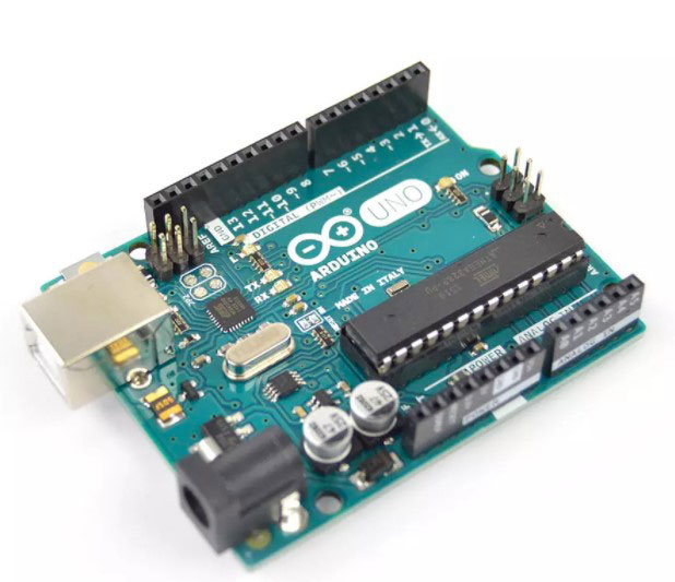
Arduino UNO development board
MFRC522 module
LCD displayer
The MI card
Due to the serial communication in the Arduino demo program, it is better to operate the displayer through serial ports.
And I just have a serial LCD displayer screen at home, which is also very convenient and easy to use, which will be introduced later.
Hardware
There are three electronic modules in the project, which I will introduce one by one.
MFRC522
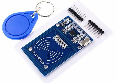
MFRC522 is a low-voltage, low-cost, small contactless read-write card chip launched by NXP, which is the choice for the development of smart meters and portable handheld devices.
Using advanced modulation and demodulation concepts, MFRC522 fully integrates all types of passive contactless communication modes and protocols at 13.56MHz.Support multi - layer application of ISO14443A.The internal transmitter section drives the reader antenna to communicate with the ISO14443A/MIFARE card and transponder without the need for additional circuits.The receiver section provides a robust and efficient demodulation and decoding circuit for processing ISO14443A compliant transponder signals.The digital part handles ISO14443A frames and error detection (parity &CRC).MFRC522 supports MIFARE higher speed contactless communication, with two-way data transmission rate up to 424kbit/s.
Purchase link: https://detail.tmall.com/
Features
- High integration modulation and demodulation circuit;
- Support ISO/IEC 14443 TypeA and MIFARE Communication protocol;
- The communication distance with ISO 14443A/MIFARE in reader mode is up to 50mm, depending on the length of the antenna.
- Supports higher transmission rates of ISO 14443 212kbit/s and 424kbit/s.
- SPI interface for 10Mbit/s
- 64 byte send and receive FIFO buffer;
- Built-in temperature sensor to automatically stop RF emission when chip temperature is too high;
- Adopt independent multi-group power supply to avoid interference between modules and improve work stability.
- CRC and parity check function.
- Internal oscillator connected to 27.12mhz crystal;
- 2.5-3.3v low voltage and low power consumption design;
- Operating temperature range: -30 ~ +85℃;
- Super small size 5mm×5mm×0.85mm.
Application
MFRC522 is suitable for a variety of applications based on ISO/IEC 14443A and requiring low cost, small size, high performance, and single power contactless communication.
- Public transport terminal
- Portable handheld device
- Contactless public telephone
- Door lock
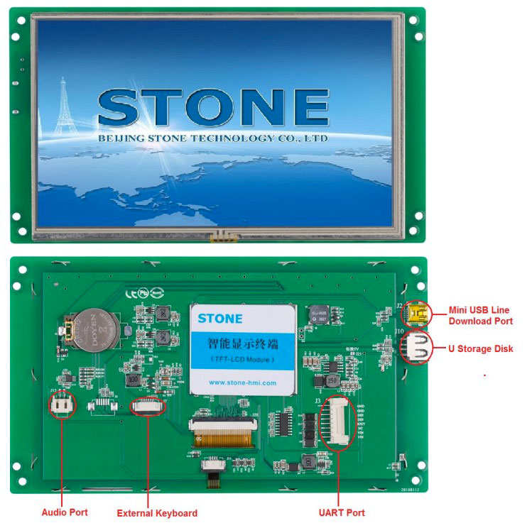
STONE STVC050WT-01
LCD-TFT display module
In this project, I intend to use the STONE STVC050WT display screen to display the card data read by MFRC522.
The driver chip has been integrated inside the display screen, and there is a development software that can be used by users. Users only need to add buttons and text boxes to the designed UI pictures through the pc, and then generate configuration files and download them into the displayer module.
The STVC050WT-01 communicates with the MCU via a uart-ttl signal.
The official website has detailed information and introduction:https://www.stoneitech.com/
If you need video tutorials, you can also find them on the official website.
Development steps
Three steps of STONE display screen development:
- Design the display logic and button logic with STONE TOOL software, and download the design file to the display module.
- MCU communicates with STONE LCD display module through serial port.
- With the data obtained in step 2, the MCU does other actions.
STONE TOOL
Download the latest version of the STONE TOOL software (currently TOOL2019) from the website, and install it.
After the software is installed, the following interface will be opened:
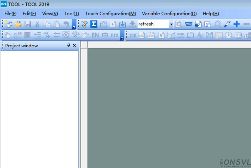
Click the "File" button in the upper left corner to create a new project, which we will discuss later.
Arduino
Developers do not need to care about the tedious details of single-chip programming, providing you with an easy to use kit.Arduino also simplifies the work process of microcontroller, but compared with other systems, Arduino is more advantageous in many places, especially suitable for teachers, students and amateurs:
- Cheap -- Arduino boards are really cheap compared to other platforms.The cheapest version of Arduino can be made with your own hands, and even an assembled product costs no more than 200 yuan.
- Simple programming environment -- Arduino programming environment is easy for beginners to learn to use, and it can provide enough advanced applications for advanced users.
- Software is open source and extensible - Arduino software is open source and can be extended by experienced programmers.The Arduino programming language can be extended through the C++ library,
- Open source and extensible hardware -- Arduino board is based on ATMEGA8 and atmega168/328 microcontroller of Atmel.Arduino is based on the Creative Commons license, so experienced circuit designers can design their own modules to extend or improve on the requirements.Even for some relatively inexperienced users, you can make test boards to understand how Arduino works, which saves money and time.
Arduino, based on AVR platform, compiles and encapsulates AVR libraries twice. Ports are packaged, and registers, address Pointers and other things are not needed.Greatly reduce the difficulty of software development, suitable for non-professional enthusiasts to use.
The development environment
Arduino IDE is very easy for beginners to learn and has plenty of flexibility.Arduino language is developed based on wiring language, which is a second packaging of avr-gcc library. It does not need too much foundation of SCM or programming, so you can develop it quickly after simple learning.
The Arduino development environment is the Arduino IDE, which can be downloaded from the Internet.
After installing the Arduino IDE, the following interface will appear when you open the software:
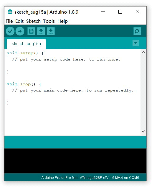
The Arduino IDE creates two functions by default: the setup function and the loop function.
There are a lot of Arduino introductions on the Internet. If you don't understand, you can go to the Internet to look up materials.
Arduino LCD Project implementation process
Hardware connection
To ensure that the next step in writing code goes smoothly, we must first determine the reliability of the hardware connection.
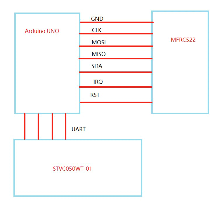
Only three pieces of hardware were used in this project:
- Arduino UNO development board
- STONE STVC050WT TFT-LCD displayer
- MFRC522 module
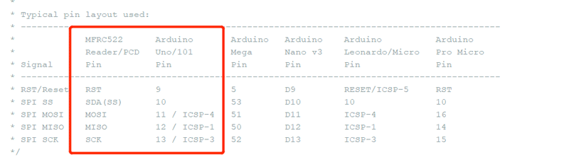
Arduino UNO development board and STVC050WT tft-lcd display screen are connected through UART, and Arduino UNO development board is connected with MFRC522 module through SPI interface.After thinking clearly, we can draw the following wiring picture:
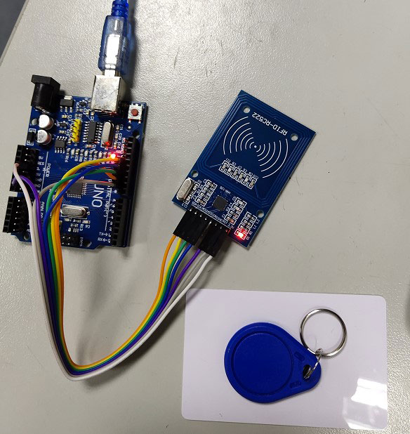
Make sure there are no errors in the hardware connection and proceed to the next step.
LCD-TFT user interface design
First of all, we need to design a picture, which can be designed by PhotoShop or other image design tools. After designing the picture, save the picture as JPG format.
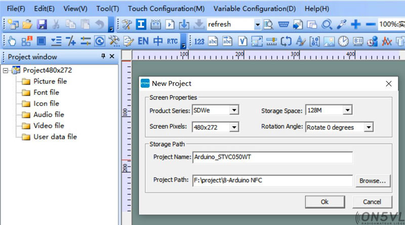
Open the software STONE TOOL2019 and create a new project:
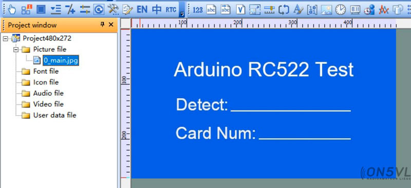
Add the text display component, design the display digit and decimal point, get the storage location of the text display component in the display screen.
The effect is as follows:
Generate configuration file
Once the UI design is complete, the configuration file can be generated and downloaded to the STVC050WT display, which is described in STONE's development materials.
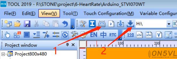
First perform step 1, then insert the usb flash drive into the computer, and the disk symbol will be displayed. Then click "Download to u-disk" to Download the configuration file onto the usb flash drive, and then insert the usb flash drive into STVC050WT to complete the upgrade.
MFRC522
We don't need to program the MFRC522 module. We just need to make sure that the hardware is connected reliably.
Arduino
Open the Arduino IDE and find the following buttons:
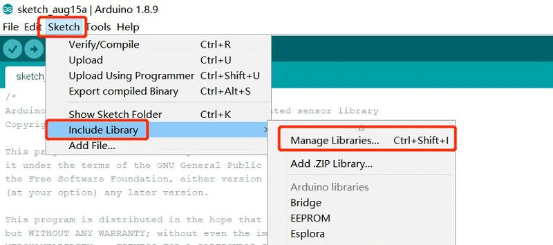
Search "RC522" to find the RC522 library file, then click download and install.
You can also download it directly from the Internet: https://github.com/miguelbalboa/rfid
After the installation, you can find the Demo of MFRC522 in the LIB library folder of Arduino:
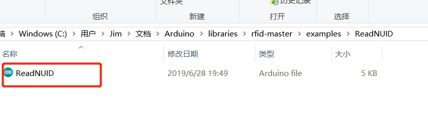
Double-click the file to open it.
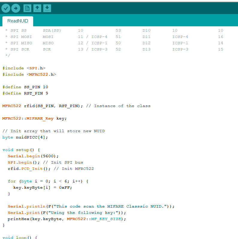
This Demo can be directly tested. After compiling and downloading the code into the Arduibo development board, the data of MFRC522 can be seen in the serial debugging tool if there are not any problems with the hardware connection.
The complete code is as follows:
/*
* --------------------------------------------------------------------------------------------------------------------
* Example sketch/program showing how to read new NUID from a PICC to serial.
* --------------------------------------------------------------------------------------------------------------------
* This is a MFRC522 library example; for further details and other examples see: https://github.com/miguelbalboa/rfid
*
* Example sketch/program showing how to the read data from a PICC (that is: a RFID Tag or Card) using a MFRC522 based RFID
* Reader on the Arduino SPI interface.
*
* When the Arduino and the MFRC522 module are connected (see the pin layout below), load this sketch into Arduino IDE
* then verify/compile and upload it. To see the output: use Tools, Serial Monitor of the IDE (hit Ctrl+Shft+M). When
* you present a PICC (that is: a RFID Tag or Card) at reading distance of the MFRC522 Reader/PCD, the serial output
* will show the type, and the NUID if a new card has been detected. Note: you may see "Timeout in communication" messages
* when removing the PICC from reading distance too early.
*
* @license Released into the public domain.
*
*/
#include <SPI.h>
#include <MFRC522.h>
#define SS_PIN 10
#define RST_PIN 9
MFRC522 rfid(SS_PIN, RST_PIN); // Instance of the class
MFRC522::MIFARE_Key key;
// Init array that will store new NUID
byte nuidPICC[4];
void setup() {
Serial.begin(9600);
SPI.begin(); // Init SPI bus
rfid.PCD_Init(); // Init MFRC522
for (byte i = 0; i < 6; i++) {
key.keyByte[i] = 0xFF;
}
Serial.println(F("This code scan the MIFARE Classsic NUID."));
Serial.print(F("Using the following key:"));
printHex(key.keyByte, MFRC522::MF_KEY_SIZE);
}
void loop() {
// Reset the loop if no new card present on the sensor/reader. This saves the entire process when idle.
if ( ! rfid.PICC_IsNewCardPresent())
return;
// Verify if the NUID has been readed
if ( ! rfid.PICC_ReadCardSerial())
return;
Serial.print(F("PICC type: "));
MFRC522::PICC_Type piccType = rfid.PICC_GetType(rfid.uid.sak);
Serial.println(rfid.PICC_GetTypeName(piccType));
// Check is the PICC of Classic MIFARE type
if (piccType != MFRC522::PICC_TYPE_MIFARE_MINI &&
piccType != MFRC522::PICC_TYPE_MIFARE_1K &&
piccType != MFRC522::PICC_TYPE_MIFARE_4K) {
Serial.println(F("Your tag is not of type MIFARE Classic."));
return;
}
if (rfid.uid.uidByte[0] != nuidPICC[0] ||
rfid.uid.uidByte[1] != nuidPICC[1] ||
rfid.uid.uidByte[2] != nuidPICC[2] ||
rfid.uid.uidByte[3] != nuidPICC[3] ) {
Serial.println(F("A new card has been detected."));
// Store NUID into nuidPICC array
for (byte i = 0; i < 4; i++) {
nuidPICC[i] = rfid.uid.uidByte[i];
}
Serial.println(F("The NUID tag is:"));
Serial.print(F("In hex: "));
printHex(rfid.uid.uidByte, rfid.uid.size);
Serial.println();
Serial.print(F("In dec: "));
printDec(rfid.uid.uidByte, rfid.uid.size);
Serial.println();
}
else Serial.println(F("Card read previously."));
// Halt PICC
rfid.PICC_HaltA();
// Stop encryption on PCD
rfid.PCD_StopCrypto1();
}
/**
* Helper routine to dump a byte array as hex values to Serial.
*/
void printHex(byte *buffer, byte bufferSize) {
for (byte i = 0; i < bufferSize; i++) {
Serial.print(buffer[i] < 0x10 ? " 0" : " ");
Serial.print(buffer[i], HEX);
}
}
/**
* Helper routine to dump a byte array as dec values to Serial.
*/
void printDec(byte *buffer, byte bufferSize) {
for (byte i = 0; i < bufferSize; i++) {
Serial.print(buffer[i] < 0x10 ? " 0" : " ");
Serial.print(buffer[i], DEC);
}
}
Open the Arduino serial listener, and you can see the following output:
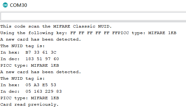
This code is very simple, I believe you can understand it at a glance. I have to say that the modular programming of Arduino is very convenient, and I don't even need to understand how the driver code of Uart and SPI is implemented.
Of course, the above code is an official Demo, and I still need to make some changes to display the data to STONE's display screen.
Display data to the STONE displayer through Arduino
First, we need to get the address of the component that displays MFRC522 data in STONE's display screen:
In my project, the address is as follows:
MFRC522 detection result output address: 0x0001
MFRC522 card result output address: 0x0004
If you need to change the display content in the corresponding space, you can change the display content by sending data to the corresponding address of the display screen through the serial port of Arduino.
The modified code is as follows:
/*
* --------------------------------------------------------------------------------------------------------------------
* Example sketch/program showing how to read new NUID from a PICC to serial.
* --------------------------------------------------------------------------------------------------------------------
* This is a MFRC522 library example; for further details and other examples see: https://github.com/miguelbalboa/rfid
*
* Example sketch/program showing how to the read data from a PICC (that is: a RFID Tag or Card) using a MFRC522 based RFID
* Reader on the Arduino SPI interface.
*
* When the Arduino and the MFRC522 module are connected (see the pin layout below), load this sketch into Arduino IDE
* then verify/compile and upload it. To see the output: use Tools, Serial Monitor of the IDE (hit Ctrl+Shft+M). When
* you present a PICC (that is: a RFID Tag or Card) at reading distance of the MFRC522 Reader/PCD, the serial output
* will show the type, and the NUID if a new card has been detected. Note: you may see "Timeout in communication" messages
* when removing the PICC from reading distance too early.
*
* @license Released into the public domain.
*
*/
#include <SPI.h>
#include <MFRC522.h>
#define read_card_addr 0x01
#define read_num_addr 0x04
unsigned char read_card_status[8]= {0xA5, 0x5A, 0x05, 0x82,\
0x00, read_card_addr, 0x00, 0x00};
unsigned char read_card_num[10]= {0xA5, 0x5A, 0x07, 0x82, 0x00, \
read_num_addr, 0x00, 0x00,0x00,0x00};
#define SS_PIN 10
#define RST_PIN 9
MFRC522 rfid(SS_PIN, RST_PIN); // Instance of the class
MFRC522::MIFARE_Key key;
// Init array that will store new NUID
byte nuidPICC[4];
void setup() {
Serial.begin(115200);
SPI.begin(); // Init SPI bus
rfid.PCD_Init(); // Init MFRC522
for (byte i = 0; i < 6; i++) {
key.keyByte[i] = 0xFF;
}
// Serial.println(F("This code scan the MIFARE Classsic NUID."));
// Serial.print(F("Using the following key:"));
// printHex(key.keyByte, MFRC522::MF_KEY_SIZE);
}
void loop() {
// Reset the loop if no new card present on the sensor/reader. This saves the entire process when idle.
if ( ! rfid.PICC_IsNewCardPresent())
return;
// Verify if the NUID has been readed
if ( ! rfid.PICC_ReadCardSerial())
return;
// Serial.print(F("PICC type: "));
MFRC522::PICC_Type piccType = rfid.PICC_GetType(rfid.uid.sak);
// Serial.println(rfid.PICC_GetTypeName(piccType));
// Check is the PICC of Classic MIFARE type
if (piccType != MFRC522::PICC_TYPE_MIFARE_MINI &&
piccType != MFRC522::PICC_TYPE_MIFARE_1K &&
piccType != MFRC522::PICC_TYPE_MIFARE_4K) {
// Serial.println(F("Your tag is not of type MIFARE Classic."));
return;
}
if (rfid.uid.uidByte[0] != nuidPICC[0] ||
rfid.uid.uidByte[1] != nuidPICC[1] ||
rfid.uid.uidByte[2] != nuidPICC[2] ||
rfid.uid.uidByte[3] != nuidPICC[3] ) {
// Serial.println(F("A new card has been detected."));
read_card_status[7]=0x01;
Serial.write(read_card_status,8);
// Store NUID into nuidPICC array
for (byte i = 0; i < 4; i++) {
nuidPICC[i] = rfid.uid.uidByte[i];
}
read_card_num[6]=rfid.uid.uidByte[0];
read_card_num[7]=rfid.uid.uidByte[1];
read_card_num[8]=rfid.uid.uidByte[2];
read_card_num[9]=rfid.uid.uidByte[3];
Serial.write(read_card_num,10);
// Serial.println(F("The NUID tag is:"));
// Serial.print(F("In hex: "));
// printHex(rfid.uid.uidByte, rfid.uid.size);
// Serial.println();
//Serial.print(F("In dec: "));
//printDec(rfid.uid.uidByte, rfid.uid.size);
//Serial.println();
}
//else Serial.println(F("Card read previously."));
// Halt PICC
rfid.PICC_HaltA();
// Stop encryption on PCD
rfid.PCD_StopCrypto1();
}
/**
* Helper routine to dump a byte array as hex values to Serial.
*/
void printHex(byte *buffer, byte bufferSize) {
for (byte i = 0; i < bufferSize; i++) {
Serial.print(buffer[i] < 0x10 ? " 0" : " ");
Serial.print(buffer[i], HEX);
}
}
/**
* Helper routine to dump a byte array as dec values to Serial.
*/
void printDec(byte *buffer, byte bufferSize) {
for (byte i = 0; i < bufferSize; i++) {
Serial.print(buffer[i] < 0x10 ? " 0" : " ");
Serial.print(buffer[i], DEC);
}
}
Compile the code, download it to the Arduino development board, and you're ready to start testing.
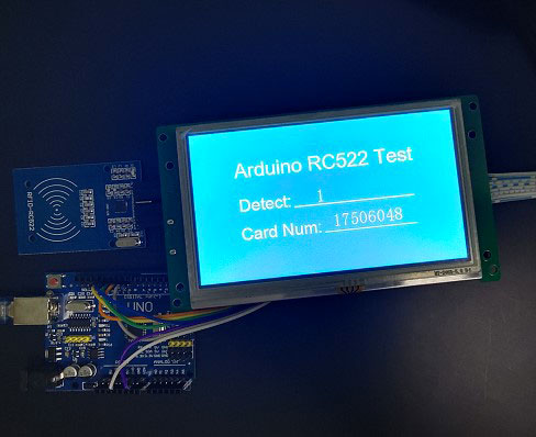
Place the M1 card on the MFRC522 collector to see the MI card number.
The effect can be seen in the following picture: